Hardware Reference
EVB Overview
The H1P EVB-B carries the HYFIX H1P GNSS/RTK module and exposes its power, data, and sensor interfaces on labeled test points and connectors (SN#) for bench evaluation.
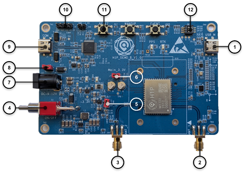
Figure 1: H1P Demo EVB B V1.0 Top View
Table 5 lists every labeled interface (SN#) shown in Figure 1, its schematic reference designator, and its function. This table is the single reference for pin/connector definitions used throughout this manual.
Table 5: Key Interfaces
| SN# | Ref. Des. | Interface / Function | Notes |
|---|---|---|---|
| 1 | USB_M | USB-NCM — WebUI / TCP-IP host interface | Data only; not a valid power source for the EVB. |
| 2 | ANT_1 | Antenna 1 (main) RF input | - |
| 3 | ANT_2 | Antenna 2 (auxiliary) RF input | - |
| 4 | S1 | Power switch (On/Off) | - |
| 5 | J46 | Jumper: antenna power (+5 V) | Remove if antenna power is not required |
| 6 | J7 | Jumper: power supply to H1P module | Factory-set; leave installed for normal operation. |
| 7 | J35 | DC power input, 9–12 V | Jumper cap SN#8 must be removed. |
| 8 | J41 | Jumper: USB power select | Installed = powered from SN#9. Removed = required for SN#7 use. |
| 9 | J1 | USB-to-UART — command / NMEA / RTCM interface | Also usable as the default power input |
| 10 | - | COM header | - |
| 11 | S2 | Reset button | - |
| 12 | SW1 | GPIO [7:5] Reserved | Factory test use only. |
Interface Applications
Dual USB Interfaces
The EVB exposes two independent, function-specific USB interfaces. They are not interchangeable.
| Interface | Purpose | Connection |
|---|---|---|
| SN#9: USB-to-UART | Serial command communication (NMEA, RTCM, commands) | Connects to the receiver's UART ports. |
| SN#1: USB NCM | Network connection (WebUI, TCP/IP) | Chip built-in USB controller |
Antenna Power Jumper Cap
Install the jumper cap at SN#5 to enable +5 V output on the main and auxiliary antenna ports for active antennas. Remove it if antenna power is not required.
Reset Button
SN#11 (S2) — active-low. Momentary press performs a hardware reset of the H1P module.
IMPORTANT NOTE
Pressing the reset button will clear all configuration, delete all files, and reboot the module. This action cannot be undone.
GPIO [7:5] Reserved
These GPIO pins are reserved for boot-mode selection. Leave in the default (Normal) state unless instructed otherwise. Full pin-state reference: Appendix B.
Antenna
ANT1 (main) and ANT2 (auxiliary, where populated) are each rated for active GNSS antenna use.
Table 7 - Active Antenna Gain and Power Consumption
| Parameter | Value |
|---|---|
| LNA gain | 18–35 dB |
| Power consumption | < 60 mA @ +5 V |
Sensors
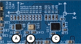
Figure 2: Sensor locations on the board
Table 8: Sensor Reference Legend
| Ref. | Sensor |
|---|---|
| A | Magnetic sensor (magnetometer) |
| B | Barometric pressure sensor |
| C | High-precision 6-axis IMU |
Power Supply
The H1P EVB accepts power from exactly one of the following sources at a time:
-
SN#9 — USB port, with Jumper cap SN#8 installed (factory default); or
-
SN#7 — DC 9-12 V input, with Jumper cap SN#8 removed
When powered via SN#7, the SN#9 USB port functions as data-only.
CRITICAL SAFETY NOTE
Never apply power to the USB connector (SN#9) and the DC 9–12 V connector (SN#7) at the same time. Simultaneous dual power sources may damage the board.