Setup Guide
USB-to-UART Driver
The EVB uses an FTDI USB-to-Serial bridge chip on SN#9. Modern operating systems (Windows 10/11) usually install FTDI Virtual COM Port (VCP) drivers automatically via Windows Update, but manual installation may be required on offline systems.
-
Drivers: Download the setup executable from the official FTDI VCP Drivers Page
-
Installation Guide: Refer to FTDI’s official FTDI Driver Installation Guides for OS-specific installation instructions.
NOTE
If your board uses the MaxLinear (XR21V1410) USB-to-Serial bridge chip, download the driver package (XR21x_Win10_V2.7.0.0.zip) from the MaxLinear support portal and manually update the four unidentified COM port devices in Device Manager.
Upon connecting the device, 4 sequential COM ports will enumerate in Device Manager under Ports (COM & LPT) (e.g., USB Serial Port (COM26) through COM29).
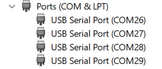
Figure 3: Device Manager confirming four COM ports
WebUI Access (USB-NCM)
The native USB interface (SN#1) presents a USB-NCM (Network Control Model) network adapter, natively supported by Windows 10/11 without a driver.
-
Connect the host PC to the EVB USB_M port (SN#1).
-
Open a web browser and navigate to http://192.168.7.1. The WebUI landing page should load:
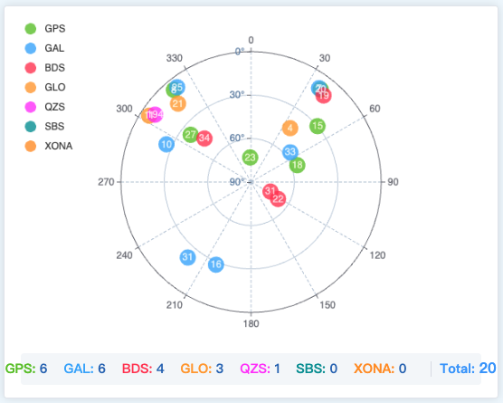
Figure 4: WebUI satellite sky plot
Firmware Upgrade
Firmware is upgraded entirely through WebUI, no external programmer is required.
-
Obtain the firmware image (.cbin) on the host PC.
-
Connect the host PC to H1P EVB via USB_M (SN#1).
-
Open Chrome, Edge, or Firefox and navigate to http://192.168.7.1.
-
Open the Upgrade menu:
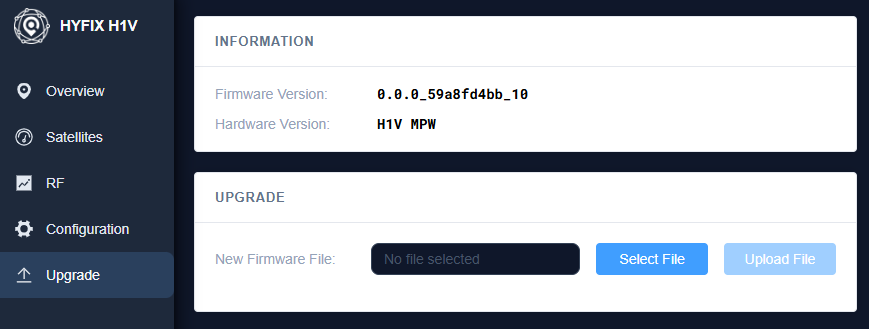
Figure 5: WebUI firmware Upgrade page
-
Click to Select File and choose the .cbin firmware image.
-
Click Upload File and wait for the upload progress bar to reach 100%. Do not close the browser tab.
-
The board reboots automatically. Wait approximately 30 seconds, then refresh the WebUI and confirm the firmware version shown matches the file you installed.
Antenna Setup
The H1P EVB-B supports two antenna configurations: single antenna positioning, or dual antenna operation for heading in addition to position. Both ANT1 (main, SN#2) and ANT2 (auxiliary, SN#3) are populated on the EVB-B — see Table 5 and Section 2.2.5 for connector locations and specifications.
Single Antenna Setup
For standard position-only operation — connect a single active GNSS antenna to the main port:
-
Connect the active GNSS antenna cable to ANT1 (main, SN#2)
-
Install the jumper cap at SN#5 to supply +5 V antenna power
-
Power on the EVB (see Power Supply & Safety, Section 1.2). Satellites should appear in the WebUI sky plot.
Dual Antenna Setup
Dual antenna operation adds a second GNSS antenna at the auxiliary port to compute heading and pitch from the baseline between the two antennas, in addition to position:
-
Connect the main antenna to ANT1 (main, SN#2) and the auxiliary antenna to ANT2 (auxiliary, SN#3)
-
Mount both antennas rigidly on the same platform with a fixed, known separation (baseline).
-
Install the jumper cap at SN#5 to supply + 5 V antenna power to both ports
-
Power on the EVB (see Power Supply & Safety, Section 1.2). Satellites should appear in the WebUI sky plot.\